
VCX Series are vertical bridge type machining centers based off our high production VP series. Big Plus 40 taper chilled spindle with high Horsepower and Large Cross Roller Guide ways.
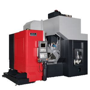
OKK VCX Series
Specifications
| Item | Unit | Specification | ||||||||||
| VC-X350 | VC-X350L | VC-X500 | ||||||||||
| Travel | Travel on X axis (Spindle head right / left) | mm | 600 (23.62″) | 700 (27,56″) | ||||||||
| Travel on Y axis (Table back / forth) | mm | 430 (16.93″) | 850 (33.46″) | |||||||||
| Travel on Z axis (Spindle head up / down) | mm | 460 (18.11″) | 610 (24.02″) | |||||||||
| Travel on A axis (Table tilting) | deg | -120 – +30 | ||||||||||
| Travel on C axis (Table turning) | deg | 360 | ||||||||||
| Distance from table top surface to spindle nose | mm | 70-530 (2.76″—20.87″) | 1 10-570 (4.33″—22.44″) | 150-760 (5.91″—29.92″) | ||||||||
| Distance from column front to spindle center | mm | 520 (20.47″) | 530 (20.87″) | |||||||||
| Table | Table work surface area | mm | Ф350 (013.78″) | 500×500 (19.69″x19.69″) | ||||||||
| Max. workpiece weight loadable on table | kg | 200 (441 lbs) | 100 (220 lbs)*1 | 500 (1102 lbs) | ||||||||
| Table work surface configuration (nominal screw-hole size x number of holes) | M10x 16 holes | M10x16 holes | ||||||||||
| Distance to the table work surface from the floor | mm | 1080 (42.52″) | 1120 (44.09″) | 1080 (42.52″) | ||||||||
| Spindle | Spindle speed | min’1 | 100-12000 | |||||||||
| Number of spindle speed change steps | Electric stepless speed change(MS) | Electric 2-step speed change(MS) | ||||||||||
| Spindle nose (nominal number) | 7/24 taper, No.40 | |||||||||||
| Spindle bearing bore diameter | mm | 65 (02.56″) | ||||||||||
| Feed Rate | Rapid traverse rate | X, Y and Z axes | m/min | XY:50 (1969 ipm) Z:36 (1417 ipm) | XY:48 (1890 ipm) Z:32 (1260 ipm) | |||||||
| A and C axes | min’1 | A:44.4 C:66.7 | A:44.4 C:100 | A:25 C:50 | ||||||||
| Cutting feed rate | X, Y and Z axes | mm/min | 1-36000 (0.04—141 7 ipm)*2 | 1-32000 (0.04-1260 ipm)*1 | ||||||||
| A and C axes | min’1 | A:44.4 C:66.7 | A:44.4 C:100 | A:25 C:50 | ||||||||
| in the turning function mode | min’1 | C:1000 | ||||||||||
| Automatic Tool Changer | Tool shank (nominal number) | JIS B6339 BT40 | BT40 Dual contact tool | |||||||||
| Pull stud (nominal number) | MAS403 P40T-1 | |||||||||||
| Number of stored tools | tool | 20 | 40 | |||||||||
| Max. tool diameter | mm | 0125 (04.92″) | Ф82 (Ф3.23″)
[ф125 (Ф4.92″) with no tools in adjacent pots] |
|||||||||
| Max. tool length (from the gauge line) | mm | 300 (11.81″) | 350 (13.78″) | |||||||||
| Max. tool weight | kg | 7 (15 lbs) | ||||||||||
| Tool selection method | Memory random method | Address fixed random method | ||||||||||
| Tool exchange time (tool-to-tool) | sec | 1.3 | 2.0 | |||||||||
| Tool exchange time (cut-to-cut) | sec | 45*3 | 4.8 | |||||||||
| Motors | for Spindle
(30-min rating/continuous rating) |
kW | 7.5/5.5 (10/7 HP) | 22/18.5 (30/25 HP) | ||||||||
| for Feed axes | X, Y and Z axes | kW | MITSUBISHI XY:2(2.7 HP) Z:3.5(4.7 HP) | MITSUBISHI X:4.5 (6 HP) YZ:3.5 (4.7 HP) | ||||||||
| FANUC XY:3 (4 HP) Z:4 (5.4 HP) | FANUC X:5.5 (7.4 HP) YZ:4.5 (6 HP) | |||||||||||
| A and C axes | kW | MITSUBISHI A:3.5 (4.7 HP) C:2.2(3 HP) | MITSUBISHI A:4.5 (6 HP) C:3.5 (4.7 HP) | |||||||||
| FANUC A:4.5(6 HP) C:2.7(3.6 HP) | FANUC A:4.5 (6 HP) C:6(8 HP) | FANUC A:5.5 (7.4 HP) C:4.5 (6 HP) | ||||||||||
| Required
Power Supply |
Power supply | kVA | MITSUBISHI^
FANUC:32 |
FANUC:32 | MITSUBISHI^ FANUC:54 | |||||||
| Supply voltage x supply frequency | VxHz | 200± 10%x50/60± 1 | 200±10%x50/60±1 | |||||||||
| 220± 10%x60± 1*4 | 220±10%x60±1 | |||||||||||
| Compressed air supply pressure | MPa | 0.5 (73 psi)*6 | 0.4—0.6 (58-87 psi)*2 | |||||||||
| Compressed air supply flow rate | L/min(ANR) | 200 (53 more gal/ipm)*6 | 200 (53 more gal/ipm)*2 | |||||||||
| Tank
Capacity |
Coolant tank | L | 280 (74 gal) | 260 (69 gal) | ||||||||
| Spindle head cooling oil tank | L | 50 (13 gal) | ||||||||||
| Hydraulic unit tank | L | 20 (5 gal) | ||||||||||
| Machine Size and
Required Floor Space |
Machine height from the floor surface | mm | 2996(117.95″) | 3076(121.10″) | 3500 (137.80″) | |||||||
| Floor space required for operation (width x depth) | mm | 1895×3440( 74.61″x 135.43″) | 3720×2450 (146.46″x96.46″) | |||||||||
| Machine weight | kg | 8500 (18700 lbs) | 12000 (26500 lbs) | |||||||||
| Temperature of operation environment | °C | 5-40 | ||||||||||
| Humidity of operation environment | % | 10-90 (No dew) | ||||||||||
| Name | Ed | Characteristics | ||||||||||
| VC-X350 | VC-X350L | VC-X500 | ||||||||||
| Traffic | Axis movement – X (Spindle head right / left) | мм | 600 (23.62″) | 700 (27,56″) | ||||||||
| Axis movement – Y (Table back / forth) | мм | 430 (16.93″) | 850 (33.46″) | |||||||||
| Axis movement – Z (Spindle Head up/down) | мм | 460 (18.11″) | 610 (24.02″) | |||||||||
| Axis movement – A (Table tilting ) | degrees | -120 – +30 | ||||||||||
| Axis movement – C (Table turning ) | degrees | 360 | ||||||||||
| Distance from table surface to spindle edge | мм | 70-530 (2.76″—20.87″) | 1 10-570 (4.33″—22.44″) | 150-760 (5.91″—29.92″) | ||||||||
| Distance from the face of the rock to the center of spindle | мм | 520 (20.47″) | 530 (20.87″) | |||||||||
| Table | Table working surface area | мм | Ф350 (013.78″) | 500×500 (19.69″x19.69″) | ||||||||
| Max. weight of the workpiece fed to the table | Kg | 200 (441 lbs) | 100 (220 lbs)*1 | 500 (1102 lbs) | ||||||||
| Configuration (nomial hole size for screws x number of holes) | M10 x 16 holes | M10 x 16 holes | ||||||||||
| Distance from floor to work surface | мм | 1080 (42.52″) | 1120 (44.09″) | 1080 (42.52″) | ||||||||
| Spindle | Spindle speed | min’1 | 100-12000 | |||||||||
| Number of changes in spindle speeds | electric infinitely variable speed (MS) |
ЭElectro 2-step speed change (MS) | ||||||||||
| Spindle edge (Nominal number) | 7/24 cone, No.40 | |||||||||||
| Spindle bearing bore diameter | мм | 65 (02.56″) | ||||||||||
| Feed rate | Fast travel speed | X, Y and Z axes | м/min | XY:50 (1969 ipm) Z:36 (1417 ipm) | XY:48 (1890 ipm) Z:32 (1260 ipm) | |||||||
| A and C axes | min’1 | A:44.4 C:66.7 | A:44.4 C:100 | A:25 C:50 | ||||||||
| Cutting feed rate | X, Y and Z axes | мм/min | 1-36000 (0.04—141 7 ipm)*2 | 1-32000 (0.04-1260 ipm)*1 | ||||||||
| A and C axes | min’1 | A:44.4 C:66.7 | A:44.4 C:100 | A:25 C:50 | ||||||||
| In swivel function mode | min’1 | C:1000 | ||||||||||
| Automatic tool change | Tool shank (Nominal number) | JIS B6339 BT40 | BT40 Double contact tool | |||||||||
| Pull rod (Nominal number) | MAS403 P40T-1 | |||||||||||
| Capacity For Tool Storage | tool | 20 | 40 | |||||||||
| Max. tool diameter | мм | 0125 (04.92″) | Ф82 (Ф3.23″)
[ф125 (Ф4.92″) Without tools in adjacent cells] |
|||||||||
| Max. tool length (From collabration line) | мм | 300 (11.81″) | 350 (13.78″) | |||||||||
| Max. weight tool | Kg | 7 (15 lbs) | ||||||||||
| Tool selection Method | Random memory method | Fixed random method address | ||||||||||
| Tool change time (from one to the other ) |
sec | 1.3 | 2.0 | |||||||||
| Tool change time (cut to cut) | sec | 45*3 | 4.8 | |||||||||
| Engines | For Spindle
(30-min. Rating / permenant rating) |
kV | 7.5/5.5 (10/7 Lс.) | 22/18.5 (30/25 Lс.) | ||||||||
| For feed axes | X, Y and Z axes | kV | MITSUBISHI XY:2(2.7 Lс.) Z:3.5(4.7 Lс.) | MITSUBISHI X:4.5 (6 HP) YZ:3.5 (4.7 Lс.) | ||||||||
| FANUC XY:3 (4 Lс.) Z:4 (5.4 HP) | FANUC X:5.5 (7.4 Lс.) YZ:4.5 (6 Lс.) | |||||||||||
| A and C осand | kV | MITSUBISHI A:3.5 (4.7 Lс.) C:2.2(3 Lс.) | MITSUBISHI A:4.5 (6 Lс.) C:3.5 (4.7 Lс.) | |||||||||
| FANUC A:4.5(6 Lс.) C:2.7(3.6 Lс.) | FANUC A:4.5 (6 Lс.) C:6(8 Lс.) | FANUC A:5.5 (7.4 Lс.) C:4.5 (6 Lс.) | ||||||||||
| Required power supply | Energy consumption | kVА | MITSUBISHI^
FANUC:32 |
FANUC:32 | MITSUBISHI^ FANUC:54 | |||||||
| Supply voltage x supply frequency | V x Hz | 200± 10%x50/60± 1 | 200±10%x50/60±1 | |||||||||
| 220± 10%x60± 1*4 | 220±10%x60±1 | |||||||||||
| Compressed air pressure | MPa | 0.5 (73 psi)*6 | 0.4—0.6 (58-87 psi)*2 | |||||||||
| Compressed air consumption | L/min (ANR) | 200 (53 more gal/ipm)*6 | 200 (53 more gal/ipm)*2 | |||||||||
| Tank capacity | For coolant tank | L | 280 (74 gal) | 260 (69 gal) | ||||||||
| Cooling Oil tank for spindle head | L | 50 (13 gal) | ||||||||||
| Hydralic unit tank | L | 20 (5 gal) | ||||||||||
| Machine size and
Space required for floor |
Machine height from floor surface | мм | 2996(117.95″) | 3076(121.10″) | 3500 (137.80″) | |||||||
| Required area (width x depth) | мм | 1895×3440( 74.61″x 135.43″) | 3720×2450 (146.46″x96.46″) | |||||||||
| Weight | Kg | 8500 (18700 lbs) | 12000 (26500 lbs) | |||||||||
| Working enviroment tempreture | °C | 5-40 | ||||||||||
| Working enviroment humidity | % | 10-90 (No dew) | ||||||||||
×